mxm-mono-00 manual
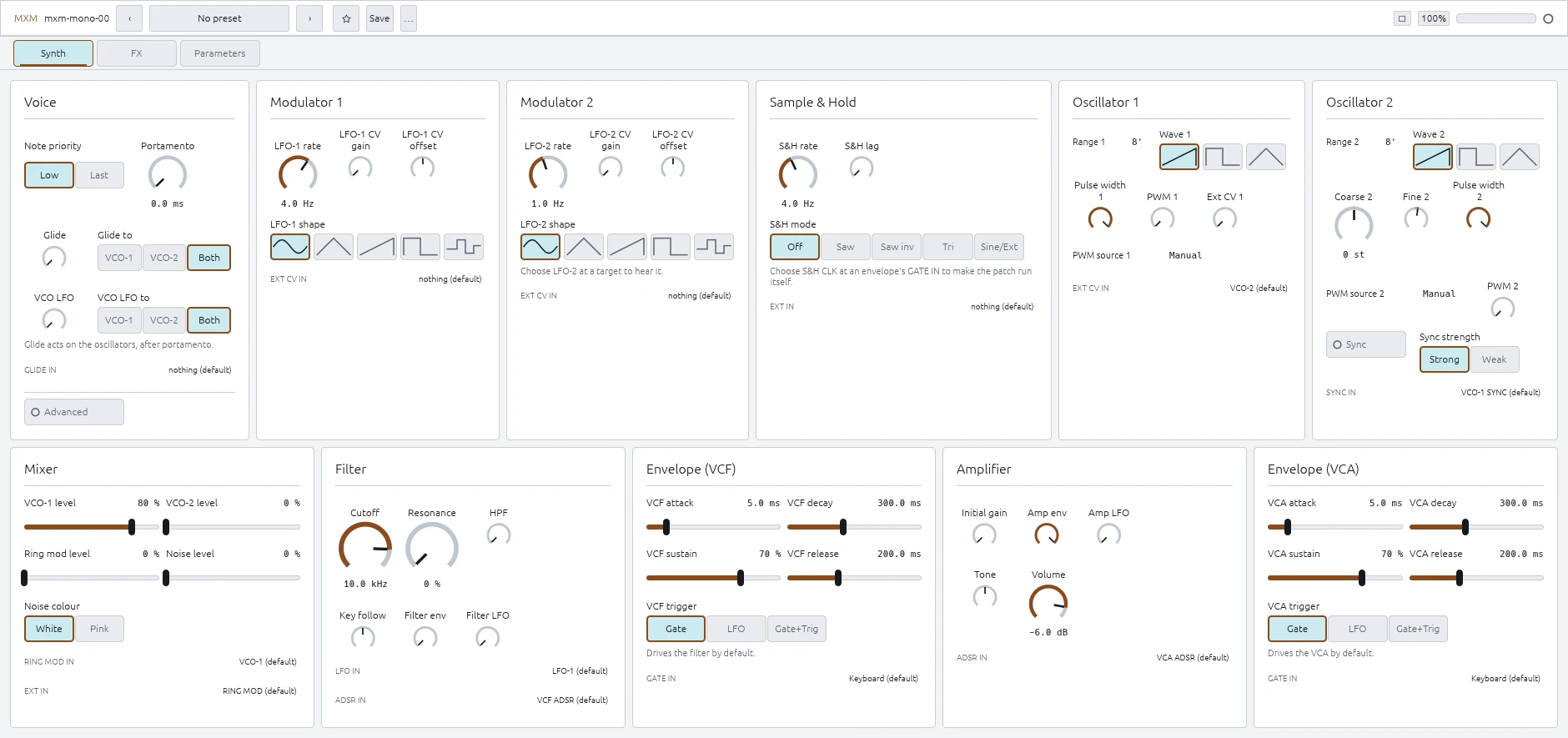
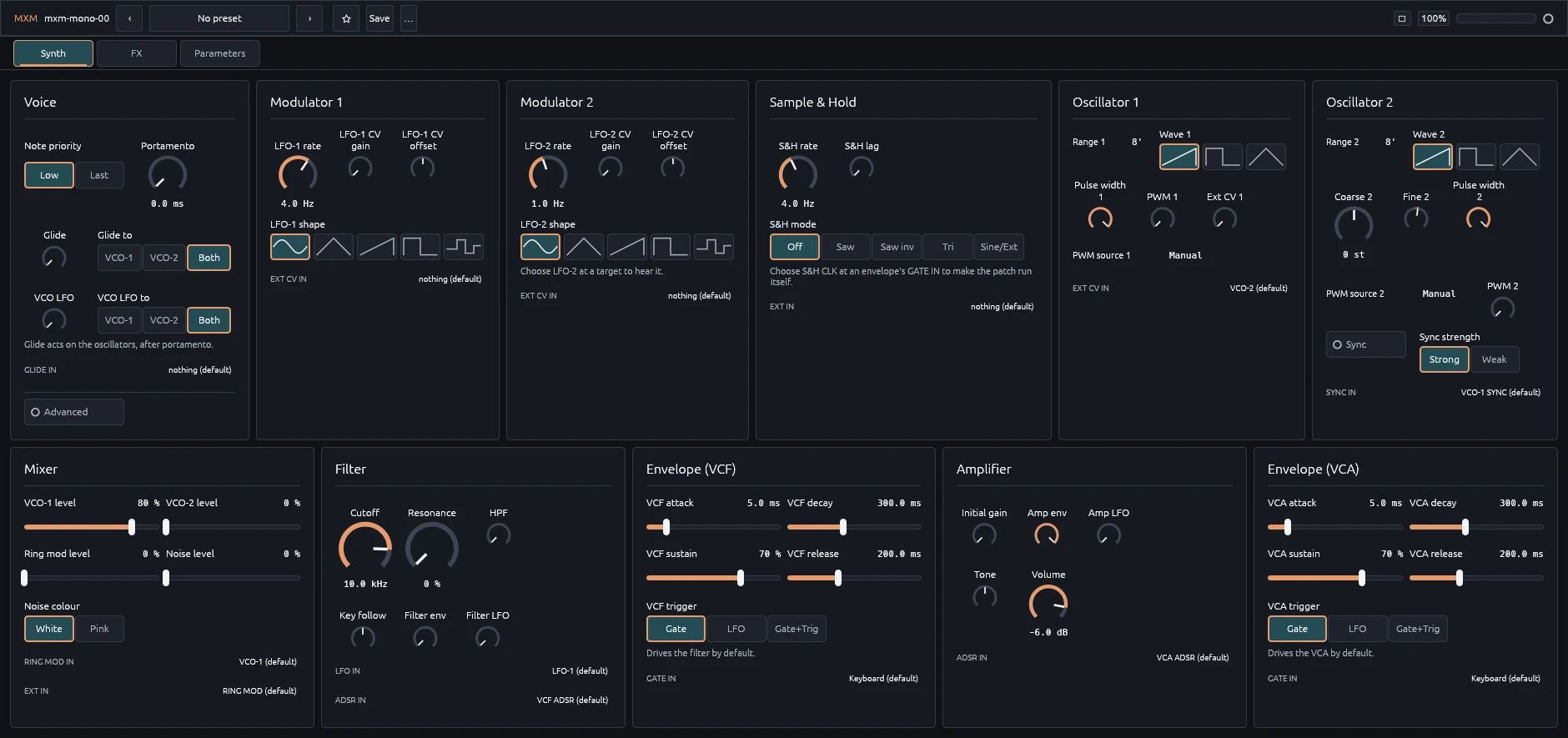
The largest MXM synth: two oscillators, two envelopes, two LFOs, sample-and-hold, three effects, and a 15-row routing matrix.
The ranges and Init values below come straight from the plugin.
Routing matrix
Each of the 15 inputs can use one of 14 sources. Choose Default to restore the normal connection. Every row is a plugin parameter, so it can be automated or locked to a step in MXM Player.
Inputs: LFO-1 EXT CV IN, LFO-2 EXT CV IN, S&H EXT IN, GLIDE IN, VCO-1 EXT CV IN, VCO-2 SYNC IN, RING MOD IN, MIXER EXT IN, VCF LFO IN, VCF ADSR IN, VCF ADSR GATE IN, VCA ADSR IN, VCA ADSR GATE IN, PHASER LFO IN, PHASER MANUAL IN.
Sources: KYBD CV, LFO-1, LFO-2, S&H OUT, S&H CLK, VCO-1, VCO-2, VCO-1 SYNC, VCO-2 SYNC, RING MOD, NOISE, MIXER, VCF ADSR, VCA ADSR.
Audio sources can feed control inputs. Gate inputs treat values above 0.25 as high. The Patch view lights up active cells and shows the signal moving through them.
Voice
Note priority — Low or Last, Init Low
Chooses which held note wins. Low matches the original machine.
Tune — −100.0 … +100.0 cents, Init 0.0 cents
Fine-tunes the whole synth.
Bend range — 0 … 24 st, Init 2 st
Sets pitch-bend range in semitones.
Portamento — 0.0 ms … 5.00 s, Init 0.0 ms
Sets glide time.
Glide — 0 … 100%, Init 0%
Sets how much of the glide is applied. This is separate from Portamento time, so the matrix can fade glide in and out.
Glide to — VCO-1, VCO-2, or VCO-1+2, Init VCO-1+2
Chooses which oscillators glide.
VCO LFO — 0 … 100% (0 … 12 semitones), Init 0%
Sets vibrato depth.
VCO LFO to — VCO-1, VCO-2, or VCO-1+2, Init VCO-1+2
Chooses which oscillators receive vibrato.
Oscillator 1
Range 1 — 64’, 32’, 16’, 8’, 4’, or 2’, Init 8'
Sets VCO-1’s octave.
Wave 1 — Sawtooth, Square, or Triangle, Init Sawtooth
Chooses VCO-1’s waveform.
Pulse width 1 — 5 … 50%, Init 50%
Sets duty cycle. 50% is square.
PWM source 1 — Manual, LFO-1, Glide, VCF ADSR, VCA ADSR, or LFO-2, Init Manual
Chooses what moves VCO-1’s pulse width.
PWM 1 — 0 … 100%, Init 0%
Sets VCO-1’s pulse-width modulation depth.
Ext CV 1 — 0 … 100%, Init 0%
Sets how much VCO-1 EXT CV IN moves VCO-1’s pitch.
Oscillator 2
Range 2 — 64’, 32’, 16’, 8’, 4’, or 2’, Init 8'
Sets VCO-2’s octave.
Coarse 2 — −24 … +24 st, Init 0 st
Tunes VCO-2 by up to two octaves in semitone steps.
Fine 2 — −100.0 … +100.0 cents, Init 7.0 cents
Fine-tunes VCO-2. Init is seven cents sharp, ready to beat against VCO-1.
Wave 2 — Sawtooth, Square, or Triangle, Init Sawtooth
Chooses VCO-2’s waveform.
Pulse width 2 — 5 … 50%, Init 50%
Sets VCO-2’s duty cycle.
PWM source 2 — Manual, LFO-1, Glide, VCF ADSR, VCA ADSR, or LFO-2, Init Manual
Chooses what moves VCO-2’s pulse width.
PWM 2 — 0 … 100%, Init 0%
Sets VCO-2’s pulse-width modulation depth.
Sync — Off or On, Init Off
Hard-syncs VCO-2 to VCO-1.
Sync strength — Strong or Weak, Init Strong
Strong locks at any ratio. Weak settles near musical intervals and bends between them.
Mixer
Four channels feed the filter.
VCO-1 level — 0 … 100%, Init 80%
Sets VCO-1 level.
VCO-2 level — 0 … 100%, Init 0%
Sets VCO-2 level.
Ring mod level — 0 … 100%, Init 0%
Sets ring-modulator level. Its second input comes from the routing matrix.
Noise level — 0 … 100%, Init 0%
Sets noise level.
Noise colour — White or Pink, Init White
Chooses white or darker pink noise.
Filter
A passive high-pass feeds a resonant diode ladder.
HPF — 10.0 Hz … 10.0 kHz, Init 10.0 Hz
Sets the high-pass frequency. Init is effectively bypassed.
Cutoff — 20.0 Hz … 20.0 kHz, Init 10.0 kHz
Sets the diode-ladder cutoff.
Resonance — 0 … 100%, Init 0%
Sets filter feedback. The bass gets thinner as it rises, and the filter can self-oscillate.
Key follow — −100 … +100% (−1:1 … +1:1), Init 0%
Makes the keyboard move the cutoff around middle C. Negative values close the filter as you play higher.
Filter env — 0 … 100% (0 … 7 octaves), Init 0%
Sets how far the VCF envelope moves the cutoff.
Filter LFO — 0 … 100% (0 … 4 octaves), Init 0%
Sets filter modulation depth. The matrix chooses the source.
Amplifier
Initial gain — 0 … 100%, Init 0%
Opens the amplifier without an envelope. Use it for drones and self-running patches.
Amp env — 0 … 100%, Init 100%
Sets how much the VCA envelope opens the amplifier.
Amp LFO — 0 … 100%, Init 0%
Sets tremolo depth.
Tone — −100 … +100%, Init 0%
Tilts the output darker or brighter.
VCF envelope
A full ADSR for the filter. Its signal and gate inputs are available in the matrix.
VCF attack — 0.4 ms … 10.00 s, Init 5.0 ms
Time to reach full level.
VCF decay — 0.4 ms … 10.00 s, Init 300.0 ms
Time to fall from full level to Sustain.
VCF sustain — 0 … 100%, Init 70%
Level held while the gate is high.
VCF release — 0.4 ms … 10.00 s, Init 200.0 ms
Time to fade after the gate closes.
VCF trigger — Gate, LFO, or Gate+Trig, Init Gate
Chooses what restarts the envelope. LFO can retrigger it while a note is held.
VCA envelope
A separate ADSR for the amplifier.
VCA attack — 0.4 ms … 10.00 s, Init 5.0 ms
Time to reach full level.
VCA decay — 0.4 ms … 10.00 s, Init 300.0 ms
Time to fall from full level to Sustain.
VCA sustain — 0 … 100%, Init 70%
Level held while the gate is high.
VCA release — 0.4 ms … 10.00 s, Init 200.0 ms
Time to fade after the gate closes.
VCA trigger — Gate, LFO, or Gate+Trig, Init Gate
Chooses what restarts the envelope.
Modulator 1
LFO-1 rate — 0.2 … 25.0 Hz, Init 4.0 Hz
Sets LFO-1 speed.
LFO-1 shape — Sine, Triangle, Sawtooth, Square, or S&H, Init Sine
Chooses LFO-1’s waveform.
LFO-1 CV gain — 0 … 100%, Init 0%
Sets how much LFO-1 EXT CV IN moves the rate.
LFO-1 CV offset — −2400.0 … +2400.0 cents, Init 0.0 cents
Adds up to two octaves of offset to the rate CV.
Modulator 2
LFO-2 rate — 0.2 … 25.0 Hz, Init 1.0 Hz
Sets LFO-2 speed.
LFO-2 shape — Sine, Triangle, Sawtooth, Square, or S&H, Init Sine
Chooses LFO-2’s waveform.
LFO-2 CV gain — 0 … 100%, Init 0%
Sets how much LFO-2 EXT CV IN moves the rate.
LFO-2 CV offset — −2400.0 … +2400.0 cents, Init 0.0 cents
Adds up to two octaves of offset to the rate CV.
Sample and hold
S&H rate — 0.6 … 125.0 Hz, Init 4.0 Hz
Sets the sampling clock. High values reach audio rate.
S&H lag — 0.0 ms … 2.00 s, Init 0.0 ms
Smooths the steps into glides.
S&H mode — Off, Saw, Saw (inv), Triangle, or Sine / Ext, Init Off
Chooses the sampled signal. Sine / Ext uses S&H EXT IN from the matrix. S&H CLK is also available as a matrix source.
Effects
Phaser, delay, and spring reverb run in that order.


Phaser — 0 … 100%, Init 0%
Sets phaser depth. The matrix provides its LFO and manual-position inputs.
Delay — 0 … 100%, Init 0%
Sets delay mix.
Delay time — 20.0 ms … 1.00 s, Init 375.0 ms
Sets delay time when Tempo sync is off.
Tempo sync — Off or On, Init Off
Locks the delay to the host tempo.
Reverb — 0 … 100%, Init 0%
Sets spring-reverb mix. mxm-folded-spring uses the same spring DSP and adds tank choice and feedback.
Output
Volume — −60.0 … 0.0 dB, Init −6.0 dB
Sets the final output level.
Parameters view
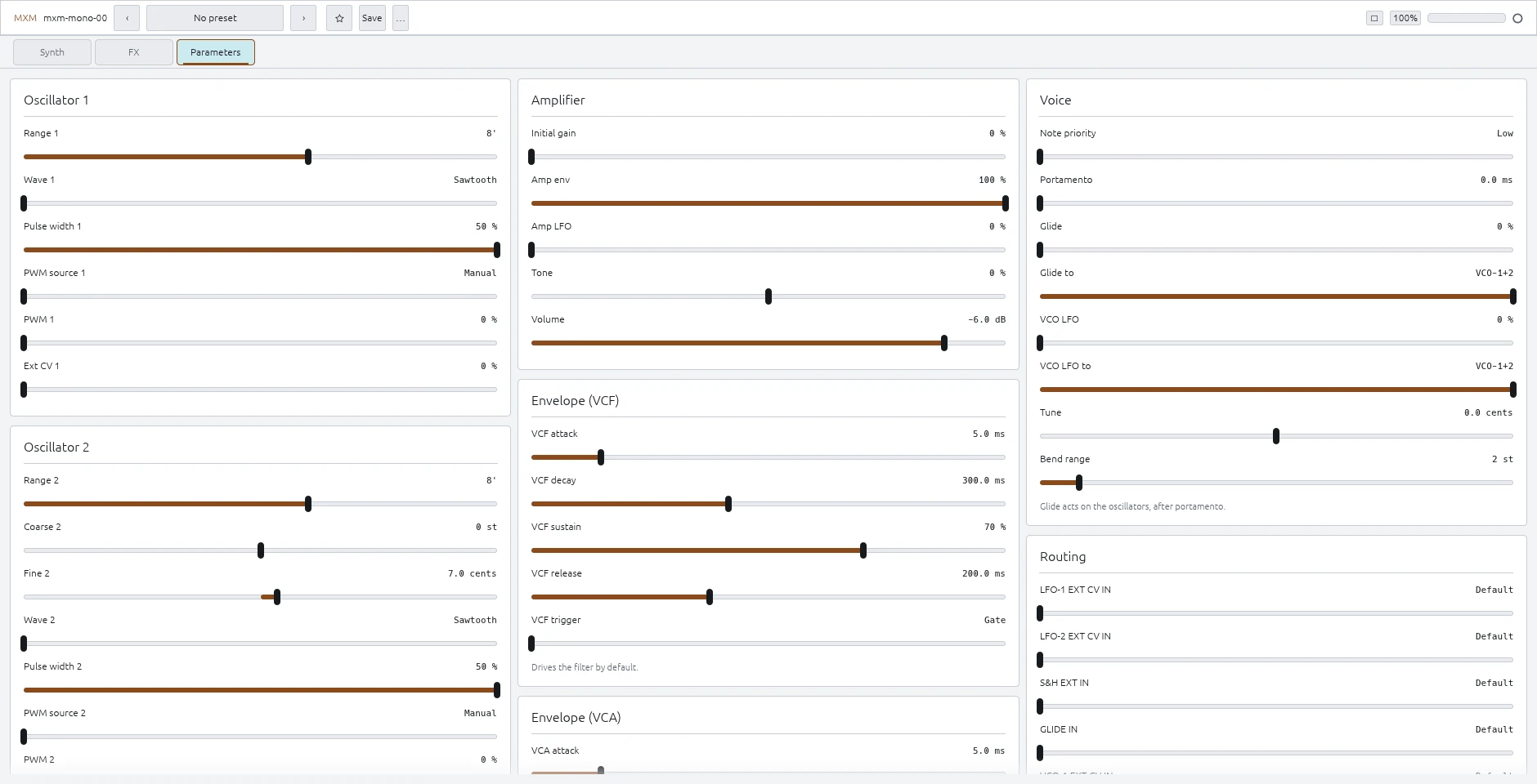
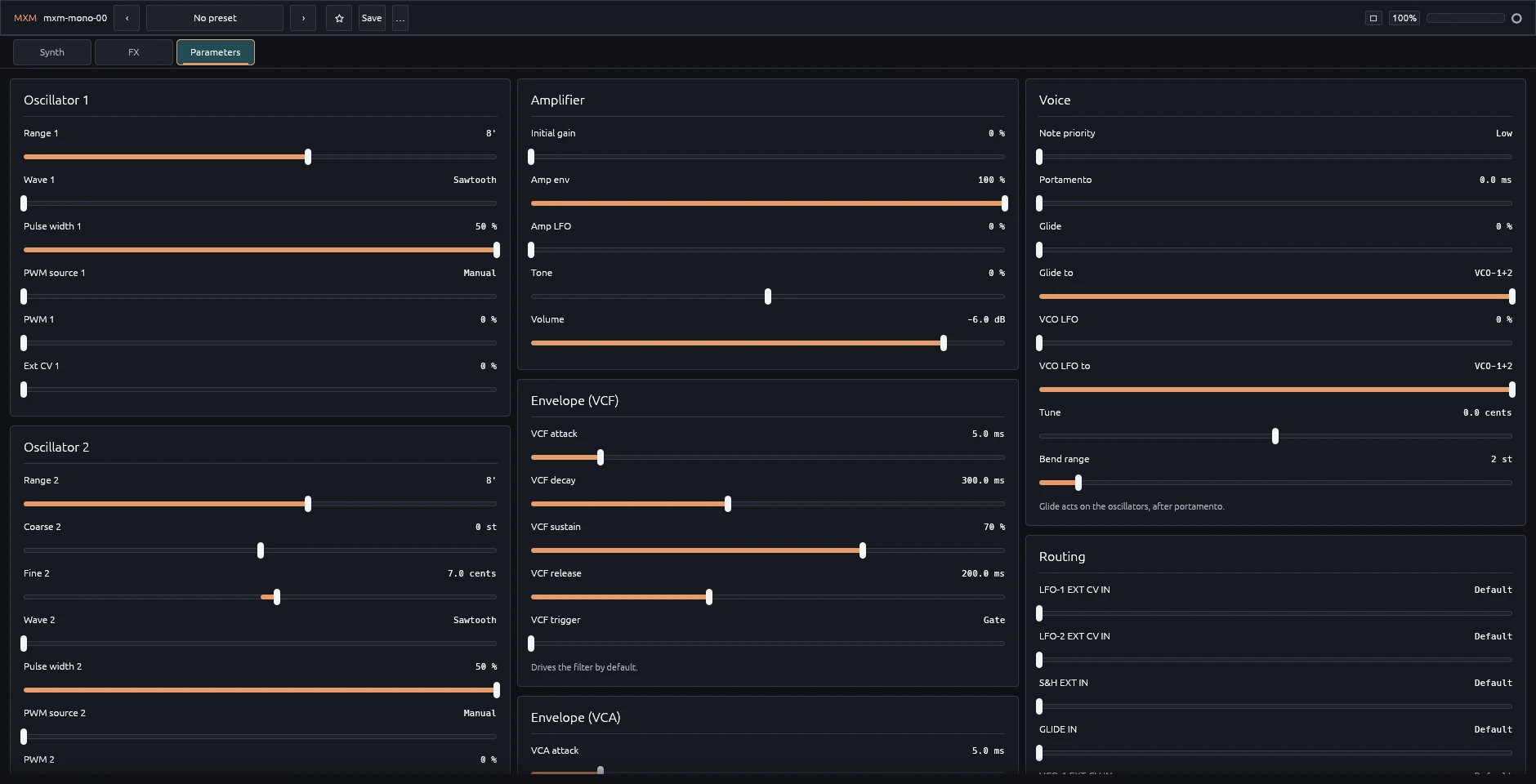
The Parameters view puts every control on one page with sliders and exact text entry.